The good material goes into the textile whilst the bad is sucked away – tape monitoring based on the “Cinderella” principle
Monitoring and automatic removal of damaged tapes on carbon multiaxial warp knitting machines
The automotive sector produces demanding products and is therefore extremely demanding itself, especially when it comes to automation and online quality assurance.
These high demands require dynamic innovation, especially on machines for producing reinforcing textiles. This is because the increasing use of lightweight components reinforced with textiles is offering huge opportunities in the automotive sector. Products manufactured on KARL MAYER’s carbon multiaxial warp knitting machines have become firmly established among fibre-based reinforcements. The textiles are made from completely straight carbon filament yarns, which produce relatively low weights in relation to the yarn count – a factor that makes them ideal for producing low, homogeneous grammages and high-quality carbon reinforcing textiles. The quality of these high-end textiles is increased even more by using expensive, high-performance carbon filament yarns. To produce these demanding, semi-finished textile components, several relatively coarse carbon filament yarns are spread out and brought together to form tapes. These tapes are fed to the carbon multiaxial warp knitting machine, laid on top of each other in one or several layers, and fixed in place at the stitch-bonding point – a well-thought-out process that enables the exceptional characteristics of the carbon filaments to be utilised optimally - as long as the quality of the feed material is good.
Early detection rather than subsequent rectification
In order to meet the stringent requirements of the automotive sector in particular, it is important that no defective tape gets into the semi-finished textile product. Defective areas must be detected when the tape is being fed in, and the relevant areas in the tape have to be removed. Reliable detection and monitoring are needed here, and this principle has been solved successfully by KARL MAYER’s Technical Textiles Business Unit in the shape of a new piece of equipment that it has developed for carbon multiaxial warp knitting machines. This innovative quality assurance system permits the efficient detection and monitoring of gaps and their lengthwise and widthwise spread across the width of the tape, faulty individual rovings, and defects at the end of the tape, i.e. colour markings on the tape separating paper.
Furthermore, a damaged area in the tape that has been detected is removed automatically by a suction device. The automatic removal process is initiated by the operator or via the software.
The early detection and removal of damaged tape areas simplify and optimise quality assurance. This improves the quality of the semi-finished products and reduces the number of faults. The volume of rejects and waste is lower and savings can be made in costs and resources.
Two control systems for multiple monitoring
The quality of the tape is monitored before the carbon material is fed into the machine, i.e. before the tape is laid from the sectional warp beams (SWBs) or from the online carbon spreading creel into the transport chain of the carbon multiaxial warp knitting machine. Two control systems are available for carrying out this initial check.
The first monitoring system operates with a sensor for detecting the colour. It identifies the end of the tape as a function of its programming mode, and reliably ensures that a tape is delivered for processing. Alternatively, the system can detect colour markings on the tape separating paper that is used during offline spreading. The sensor can distinguish between up to three colours. If one of them is detected, the carbon multiaxial warp knitting machine reacts on the basis of the customer’s own specific requirements.
A second control system also detects whether there are any gaps in the carbon tape and how big they are, and it also detects whether there are any faults in individual rovings. The tape width is also monitored – an all-round check that is carried out by high-tech systems. The monitoring system also consists of cameras (Fig. 1), illuminating devices and an image processing system.
In addition to initiating the removal process or machine stoppage when the tolerance limits have been exceeded, it is also possible to store in a file the measured values and the associated information relating to the number of metres.
Reliable elimination of faults using an automatic removal system
If the quality monitoring systems detect that the tolerance values stipulated by the customer have been exceeded, the machine stops and the process for rectifying the fault is initiated. Depending on the nature of the fault, the SWP is replaced or the faulty tape is cut and sucked away. The defective tape is removed by a gripper stroke and suction device at the laying-in device until the moment that a perfect tape is fed in. The process takes place in accordance with a strict sequence, which runs as follows.
Once a defect has been detected, the machine stops and the operator initiates the automatic removal sequence by activating a switch or via a software signal. In the operating state for dealing with faults, the gripper first of all grips the tape (Fig. 2) until the camera system detects the end of the fault, or the minimum removal length or maximum gripper lift (working width) has been reached. The gripper stroke can also be interrupted by the operator. The tape is then clamped at the operator side, the suction device is started and the gripper moves towards the suction box. The suction device then grips the tape (Fig. 3). This tensions the carbon tape between the gripper, the clamp and the air flow of the suction device (Fig. 4). The gripper stops just in front of the suction box and releases one of its two ends ready for suction (Fig. 5). The tape is then cut at the clamp (Fig. 6) so that the other end can be sucked away at the operator or A-side of the machine.
In order to continue the production process, the empty gripper then moves to this side of the machine to grip a new tape (Fig. 7).
Optimised components result in accurate processes
To guarantee that the suction sequence operates accurately, the suction box must be designed optimally in terms of the air flow, the width of the tape being processed, and especially with regard to the laying angle. Two different laying angle systems are available. On the one hand, different angle-specific suction-box tops are available for customers operating with a few, fixed laying angles. The top part of the suction box can be fixed or changed quickly and reliably using adjustment pins with specific bores.
On the other hand, KARL MAYER can supply customers needing greater flexibility with a suction-box top that offers free adjustment of the angle. This system also enables the angle to be changed quickly and easily.
A contribution to automation
KARL MAYER’s Technical Textiles Business Unit is offering an innovative quality assurance system in the shape of the automatic tape removal system, which improves the quality of the textile, reduces waste and lowers costs. Defective tapes are sucked away reliably and the angle can be changed quickly and easily – features that make the system reliable and flexible.
With this latest innovation, KARL MAYER is also meeting a fundamental customer requirement – the need for machines to operate at a high level of automation. Further automation processes are currently at the planning stage, and will be presented once the development work has been completed.
Back to overview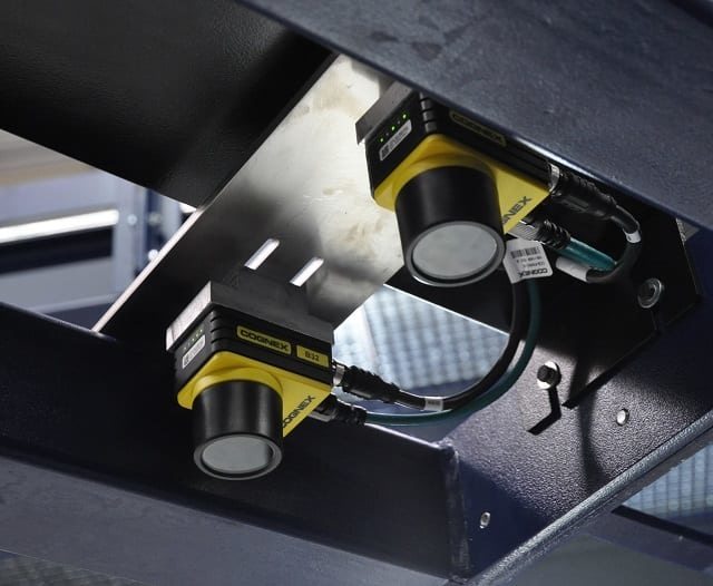
Fig. 1: The cameras of the quality assurance system
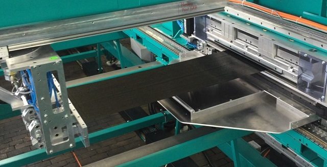
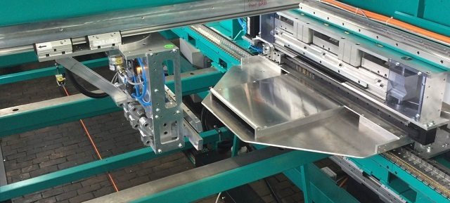
Fig. 2: The gripper moves with the tape across the working width

Fig. 3: The moment of tape suction
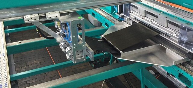
Fig. 4: The tape during suction
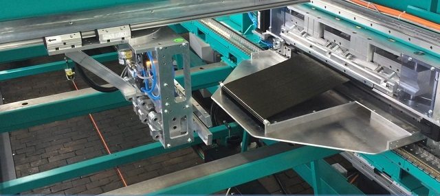
Fig. 5: The first end is sucked away
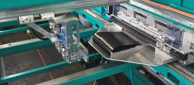
Fig. 6: The second end is cut